

-
llámanos
0086 13559245184 -
Envíanos un correo electrónico
sales@fortunepart.com
llámanos
0086 13559245184Envíanos un correo electrónico
sales@fortunepart.com
Sep, 2026
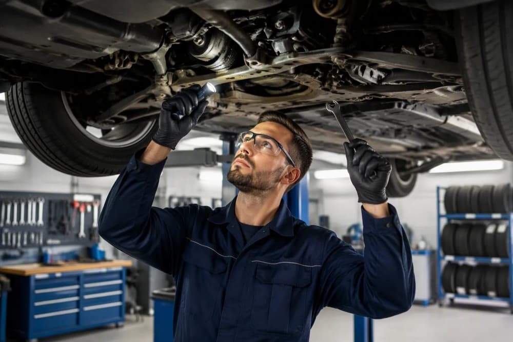
Checking undercarriage wear and tension requires a systematic approach: prepare the machine, measure track sag, then inspect each component for wear indicators. You should perform this inspection every 250 to 500 operating hours. This maintenance routine represents the most cost-effective strategy to lengthen the life of your machine. You need basic tools, manufacturer specifications, and a methodical process. The importance of undercarriage care cannot be overstated—early detection of wear on your dozer's Track Chain prevents future downtime and saves thousands in replacement costs. Regular undercarriage maintenance protects your investment.
Inspect your undercarriage every 250 to 500 hours to catch wear early and avoid costly downtime.
Measure track sag with a straightedge and compare it to your manual's spec to set correct tension.
Check sprocket teeth, bushings, and rail height for wear; replace parts when they hit the limits.
Compare left and right sides to spot uneven wear, then fix the root cause like alignment or turning habits.
Document all measurements to predict part life and schedule replacements before failures happen.
Before you begin a detailed track inspection, you must take the correct safety precautions and gather the right tools. Your safety is the absolute priority. This section walks you through the preparation steps. A solid foundation ensures you can accuratelyinspect your machine’s undercarriage. Without proper preparation, you risk missing criticalwearon yourdozer, leading to costly failures later.
Start by positioning thedozeron firm, level ground. Engage the parking brake fully. Lower the blade and ripper to the ground to release hydraulic pressure. Turn off the engine and remove the key. Always complete a lockout/tagout procedure to prevent accidental startup. Then, put on your personal protective equipment. You must weargloves,safety glasses, andsteel-toed bootsat a minimum. This protective gear guards against sharp metal, high-pressure fluids, and heavycomponents.
Next, assemble yourinspectiontools for yourdozer. You need a track sag gauge or a straightedge with a tape measure. A caliper is useful for measuring bushing and roller diameter. You also need a depth gauge for grouser height. Most importantly, have your manufacturer’s service manual on hand. It contains the specificconditionlimits for your model. Achecklisthelps you stay organized and ensures you don’t skip a step.
Finally, clean theundercarriagethoroughly. A pressure washer works best for removing packed mud, grease, and debris. A clean machine reveals cracks, seal leaks, and metal deformation. You cannot rely on avisual inspection once a weekif dirt hides the evidence. This cleaning step is a critical part of properundercarriage maintenance. Thismaintenancepractice instantly improves the accuracy of yourvisualassessment. It allows you to see the true condition of theundercarriageand trackwearaccurately.
Start by moving the dozer to a flat, hard surface. Level ground is essential for a reliable measurement. Engage the parking brake and lower the blade to the ground. Then, roll the machine forward approximately two to three full track lengths. This action settles the track chain and removes any slack caused by the previous position. Do not move in reverse; forward motion seats the bushings correctly against the sprockets. After rolling forward, stop the engine and apply the lockout procedure. The track chain must be in a stable, tensioned state before you measure.
Now you need to measure the sag of the track chain. Use a straightedge—a long, straight piece of metal or wood works best. Place it across the top of the track shoes, spanning from the front roller to the rear roller. The straightedge should rest on the highest points of the shoes. Then, measure the vertical distance between the bottom of the straightedge and the top of the track shoes at the midpoint between the rollers. This distance is your track sag. For a typical crawler dozer, the correct sag is approximately 2.5 inches.
The recommended method for measuring track sag on a crawler dozer is to use a straight-edged object pulled along the dozer's shoes between the front and back rollers. The amount of sag in the middle should then be measured, with the correct amount being approximately 2.5 inches.
Record the sag measurement. Repeat this process on the other side of the machine. Compare both readings to identify any imbalance.
Take your recorded sag measurement and compare it to the specification in your equipment manual. Every dozer model has a specific acceptable range. If the sag is greater than the spec, the track is too loose. If the sag is less than the spec, the track is too tight. An over-tensioned track chain causes several problems:
It increases the load on rollers, leading to rapid flange and tread wear.
It raises fuel consumption due to higher friction.
It puts unnecessary stress on idlers and sprockets.
Avoid over-tightening the track chain, as it increases internal stress within the chain components.
If the sag falls outside the spec, you must perform a track adjustment. Use the grease fitting or hydraulic cylinder to add or release grease until the sag matches the manufacturer’s value. Never operate the dozer with incorrect tension; it will accelerate wear throughout the entire undercarriage system.
Once you confirm the sag measurement falls outside the manufacturer's specification, you must perform a track adjustment. Locate the grease fitting on the front of the track frame, near the idler. For most dozer models, you use a grease gun to add pressure or a release valve to remove it. The hydraulic cylinder behind the idler extends or retracts the idler to change the track tension. You add grease to tighten the track. You release grease to loosen it. Work in small increments—one or two pumps at a time—then re-measure the sag. This methodical approach prevents you from overshooting the correct setting.
Several common errors can ruin your track adjustment before you finish. Avoid these mistakes to ensure accurate results:
Measuring on uneven ground: A machine on a slope or soft surface distributes weight unevenly. This condition alters the sag reading and leads to incorrect tension.
Failing to settle the track: You must drive the dozer forward and coast to a stop. This action pulls the upper track span taut. Reversing into position leaves slack in the chain, producing a false measurement.
Misreading the packing condition: Deep mud, clay, or snow packs into the undercarriage during operation. This material tightens the track as you work. You need a looser initial setting for these conditions. Standard tension in packed environments causes severe over-tensioning once the material compacts.
The consequences of incorrect tension extend beyond poor performance. You face distinct problems with each extreme:
Over-tensioning (too tight):
Causes power loss and fuel waste from increased friction in pin and bushing joints
Accelerates wear on bushings, sprocket teeth, rollers, idlers, and bearings
Places excessive static load on the recoil spring, shortening its service life
Under-tensioning (too loose):
Risks de-tracking during turns or on slopes, causing downtime and potential damage
Leads to improper sprocket engagement, resulting in chipping and abnormal wear
Causes track links to slap roller flanges, creating scalloping damage
A common and destructive error is the belief that a tighter track is better. Over-tensioning increases friction, robbing power, raising fuel consumption, and accelerating wear on all undercarriage components. The correct approach is to always adhere to the manufacturer's specified sag measurement.
After each adjustment, roll the dozer forward again to settle the chain. Re-measure the sag to confirm the new setting. Repeat this cycle until the measurement falls within the acceptable range. Document the final reading and the amount of grease you added or released. This record helps you track how quickly your track tension changes over time. A rapid loss of tension often indicates a leaking cylinder or worn seals. A sudden increase in tension may signal a failing recoil spring. Both conditions require immediate attention from a qualified technician.
Now you move to the most critical components of thecrawler dozer undercarriage: the sprockets and thetrack chain. These parts transfer power from the drive train to the ground. Their wear directly determines when you need a major overhaul. A systematicinspectionof these parts reveals the trueconditionof yourdozer’s driveline.
Start with the sprocket teeth. You must check fordozer sprocket wearpatterns, especially the hook shape that develops over time. As thetrack chainelongates, the bushings ride higher on the tooth face. This action creates a curved, hook-like profile on the drive side of each tooth. Severe hook wear prevents proper engagement and accelerates further damage.
Use a dedicated sprocket wear gauge to measure the wear depth. TheKONE Spares Sprocket Evaluation Tool Kitis explicitly designed to measure the amount of wear on sprocket teeth, including the 'hook effect' that forms over time. This tool kit provides a way to quantify the severity of this wear, which is critical for determining whether a new chain can be installed or if the sprocket must also be replaced.
Follow these replacement guidelines for sprocket teeth:
Replacement threshold: Replace sprocket segments when the tooth is worn down to25% of its original height(per OEM rule of thumb).
Measurement method 1: Use a sprocket wear gauge for a direct go/no-go reading.
Measurement method 2: Use calipers to compare worn teeth against a new segment or OEM blueprint.
Maintenance practice: Establish a baseline measurement for new segments and log wear rates regularly to predict replacement intervals.
Now examine the engagement between the sprocket and the chain.Pitch elongationin thetrack chaincauses misalignment. When track pitch elongates beyond sprocket pitch, the chain cannot seat correctly at every engagement point. Bushings may contact the upper part of sprocket teeth or place heavier load on one side of a tooth. Elongation increases the distance between engagement points, causing bushings to misalign with sprocket pockets under torque. This leads to uneven contact, impact loading, hooked sprocket teeth, abnormal wear, and increased risk of chain jumping. Measure the pin-to-pin distance across several links to detect elongation. Compare your measurement against the factory specification.
Next, inspect the bushings on thetrack chain. The bushing is the cylindrical component that rides against the sprocket teeth. Constant contact flattens the outer diameter of the bushing over time. You can measure thisbulldozer track wearusing a caliper. Place the caliper jaws across the bushing at the contact point. Compare the reading to the bushing diameter on a new chain. A flattened bushing reduces the sprocket engagement area, increasing stress on both parts.
Look for pin wear at the same time. The pin connects each link pair. Wear occurs between the pin and the bushing inner surface. This internal wear is not visible directly, but you can infer it from thetrack chain’s overall stretch. Measure the chain pitch across a known number of links. If the pitch exceeds the maximum allowable limit, the pin and bushing assembly is worn out. Replace the chain before the pins break or the bushings crack.
The C rail is the flat surface on the top of the track chain links that the rollers ride on. The height of this rail is a critical indicator ofundercarriage wear. The critical rail height measurement for a Caterpillar undercarriage indicating replacement is when the rail height measuresless than 75% of the original new height. This threshold is defined as a sign of high wear, meaning that once the rail wears down to below this percentage, replacement is required.
You measure the rail height with a depth gauge or a caliper. Place the tool on the top of the rail and measure the vertical distance to the top of the link. Record the measurement for each link in a representative section of the chain. A consistent low reading indicates uniform wear across the chain. A sudden drop in one link points to a localized defect.
Track stretch complements the rail height measurement. To calculate stretch, measure the overall length of thetrack chainover a set number of links. For example, measure the distance from the center of the first pin to the center of the 50th pin. Divide the result by the number of links to get the average pitch. Compare this average to the original pitch from the manufacturer. The percentage difference between the two values is the wear percentage. When the wear percentage exceeds 2–3% (depending on the OEM), the chain is at the end of its service life.
Do not rely solely on one measurement. The combination ofdozer sprocket wear, bushing flattening, rail height, and track stretch gives you a complete picture of thecrawler dozer undercarriage wearcondition. Use this data to decide whether to replace individualcomponentsor the entire system. Include these measurements on yourchecklistfor everyinspectioncycle. Regularvisualchecks during operation help you catch early signs of abnormal wear before they become major failures.
The track chain links form the backbone of your crawler dozer undercarriage. These steel components bear the entire machine weight and transfer tremendous forces during operation. You must examine each link carefully for structural damage. Cracks, spalling, and side wear indicate serious problems that require immediate attention.
Inspecting for Cracks
You need a bright light and a clean surface to detect cracks effectively. Start at the link's outer face and work your way around the entire component. Pay special attention to the areas around pin bores and the transition zones between the rail surface and the link body. These locations experience the highest stress concentrations.
Small hairline cracks often appear first near the pin bore. You might miss them during a quick visual inspection. Use a magnifying glass or a dye penetrant kit for suspicious areas. Apply the penetrant, wait for it to seep into any fissures, then wipe the surface clean. The dye remains visible in cracks, making them easy to spot.
A cracked link is a catastrophic failure waiting to happen. Do not operate the dozer if you find any crack longer than 1/8 inch. Replace the affected link immediately.
Identifying Spalling
Spalling refers to small chips or flakes that break away from the link surface. This damage typically occurs on the rail surface where rollers make contact. You will notice small pits, divots, or rough patches that feel different from the surrounding smooth metal.
Spalling develops from surface fatigue. Repeated loading and unloading cycles cause microscopic cracks to form beneath the surface. These cracks eventually propagate to the surface, causing material to break away. You should measure the depth and width of any spalled areas. Shallow spalling less than 1/16 inch deep may not require immediate action. Deeper spalling compromises the link's structural integrity and accelerates roller wear.
Measuring Side Wear
Side wear occurs on the inner and outer faces of the links. This wear pattern develops from contact between adjacent links and from debris trapped between them. You can measure side wear using a caliper. Place the caliper jaws against the link face and measure the thickness. Compare this reading to the original link thickness specification from your manufacturer.
Excessive side wear reduces the link's cross-sectional area. This reduction weakens the link and makes it more susceptible to bending or breaking. Side wear also increases the gap between adjacent links, allowing more debris to enter the pin and bushing area. This contamination accelerates internal wear and shortens the entire track chain's service life.
Documenting Link Condition
Record your findings for each link in a systematic manner. Note the link position, the type of damage, and the severity. Take photographs of any cracks or significant spalling. These records help you track wear progression over time and predict when replacement becomes necessary.
You should also compare links across both sides of the machine. Uneven damage patterns between left and right track chains often indicate alignment issues or operational habits that need correction. For example, consistent spalling on one side may point to a worn roller or idler on that side.
Regular link inspection forms a critical part of your overall check crawler dozer undercarriage wear routine. The condition of your links directly affects the performance and safety of your entire machine. A thorough inspection of crawler dozer undercarriage wear includes examining every link for these three damage types. You cannot afford to skip this step in your maintenance schedule.
Remember that bulldozer track wear manifests in multiple ways across different components. The links often show the earliest signs of trouble. Catching link damage early prevents more extensive damage to rollers, sprockets, and the final drive. Your attention to these details determines whether you face a minor repair or a complete undercarriage replacement.
The dozer sprocket wear you checked earlier connects directly to link condition. A worn sprocket places abnormal stress on the links, accelerating crack formation and spalling. Address sprocket issues promptly to protect your track chain investment. Your dozer depends on a healthy undercarriage for reliable operation. Make link inspection a non-negotiable part of every maintenance session.
After completing your sprocket and chain evaluation, you must shift your attention to the rollers, idlers, and track shoes. These components carry the machine's weight and guide the track chain. Their condition directly affects the entire undercarriage system. A thorough inspection of these parts reveals hidden problems before they escalate into costly failures.
You begin with the rollers. These components bear the heaviest loads and show wear first. Check the flanges for missing angles and height reduction. Use a caliper to measure flange height against the original specification. The table below shows common industry thresholds for roller flange wear.
|
Wear Parameter |
Threshold |
Recommended Action |
|---|---|---|
|
Flange missing angle |
< 45° |
Continue use with monitoring |
|
Flange missing angle |
45°–90° |
Replace (especially for slope work) |
|
Flange missing angle |
> 90° |
Replace immediately |
|
Roller diameter reduction |
> 10–15% |
Replace |
|
Flange height |
< 85% of new specification |
Replace |
Note: These are common industry reference values; OEM specifications should be consulted for specific machines.
You also need to measure the roller shell thickness. Track rollers have a maximum allowable wear limit of 30–35% material loss. Exceeding this threshold leads to link rail destruction and roller shell cracking. Another source indicates a 10–15% reduction in tread diameter from the original dimension marks the point of failure. Beyond this point, the roller is worn out and at risk. Finally, inspect each roller for seal leaks. Grease or oil weeping from the seals indicates contamination or seal failure. A leaking seal allows debris to enter the bearing, accelerating internal wear.
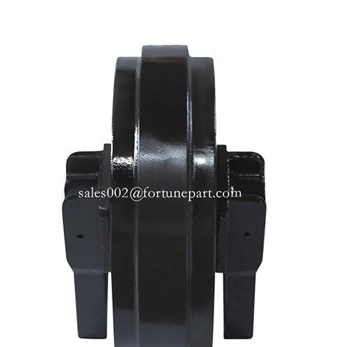
Next, you examine the idlers. These components guide the track chain at the front and rear of the machine. You must check for uneven flange wear and surface flatness. Idlers show several distinct wear indicators that point to specific problems.
Material worn from outer or inner flanges indicates misalignment, worn track roller guides, or side-slope operation.
Excessive wear on the inboard flange suggests consistent turning in one direction or side-slope work.
Center flange wear that appears thin or sharp signals misalignment or a mismatch between the idler and track chain.
You measure the idler flange thickness with a caliper. Compare your reading to the manufacturer's specification. A thin or sharp flange cannot properly guide the track chain, leading to de-tracking and further damage. You also check the idler surface for flat spots or grooves. These defects cause vibration and accelerate bulldozer track wear across the entire system.
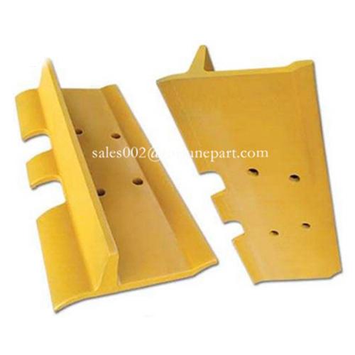
Finally, you inspect the track shoes. These components provide traction and protect the undercarriage from ground contact damage. You must check each shoe for cracks, bending, and missing hardware. Track shoe bending occurs for several reasons.
|
Reason |
Explanation |
|---|---|
|
Harsh operating environments |
Sand, cement, mud, or corrosive surfaces accelerate wear and rust; debris increases friction, causing irregular wear on the shoe body and grouser. |
|
Poor maintenance |
Lack of lubrication, loose bolts, and accumulated debris cause abnormal stress, leading to loosening or broken track chains. |
|
Substandard materials and heat treatment |
Inferior products without proper normalization or quenching lack strength and toughness, cracking under micro-fractures. |
|
Improper installation |
Uneven or insufficient torque during bolt tightening causes stress concentration; misalignment may lead to dislodging. |
|
Overloading and extended use |
Operating beyond design capacity induces premature fatigue; extended work on inclines causes uneven force, increasing the risk of bending or breakage. |
You also measure grouser height with a depth gauge. Worn grousers reduce traction and increase slippage, which accelerates wear on other components. Check every bolt and nut for tightness. Missing hardware allows shoes to shift or detach during operation. Add these component checks to your inspection checklist. Regular assessment of these parts keeps your crawler dozer undercarriage wear within acceptable limits. You must check the components systematically to maintain the overall condition of your dozer. A complete inspection covers every element of the undercarriage, ensuring you catch problems early and extend the life of your machine.
Grouser height determines your dozer's traction capability. Worn grousers reduce grip on soft ground, increase slippage, and force the machine to work harder. This extra effort accelerates wear on the entire undercarriage system. You must measure grouser height accurately to assess remaining track shoe life.
Start with a clean track shoe surface. Remove packed mud and debris from the grouser area. Place the depth gauge base flat against the shoe plate surface. Extend the measuring rod until it touches the top of the grouser. Read the measurement directly from the gauge dial or digital display. Record this value for each shoe you inspect.
You should measure at least three points along each grouser: the center, the left edge, and the right edge. Track shoes wear unevenly during operation. The center often wears faster than the edges on hard surfaces. The edges wear faster when operating on slopes or making frequent turns. Compare all three readings to identify the true condition of each shoe.
The table below shows typical grouser height specifications for common dozer classes.
|
Dozer Class |
New Grouser Height |
Replacement Threshold |
|---|---|---|
|
Small (under 150 HP) |
1.5 inches |
0.75 inches |
|
Medium (150–300 HP) |
2.0 inches |
1.0 inches |
|
Large (over 300 HP) |
2.5 inches |
1.25 inches |
Note: These values represent industry averages. Always consult your equipment manual for exact specifications.
When grouser height reaches 50% of the original dimension, replacement becomes necessary. Operating beyond this point compromises traction and increases strain on the track chain and roller components. A worn grouser also reduces the shoe's structural rigidity, making it more susceptible to bending under heavy loads.
You should also inspect the grouser tip for rounding or chipping. A sharp, square tip provides maximum bite into the ground. A rounded tip loses gripping power and causes the machine to slide on inclines. Use the depth gauge to check for uneven wear patterns that indicate alignment problems.
Document every grouser measurement in your maintenance log. Track the wear rate between inspections. A rapid decrease in grouser height signals harsh operating conditions or excessive track slippage. Address the root cause before replacing shoes prematurely. Regular grouser measurement protects your dozer investment and ensures safe, efficient operation on every job site.
You must measure every component on both track frames. For idlers, take a measurement on both sides of the center tread and average the readings. This technique reveals asymmetry between the left and right sides. You also compare roller diameter, bushing external diameter, and track chain pitch across both sides. Undercarriage wear patterns point to specific operational factors. The table below shows how these factors create uneven wear.
|
Operational Factor |
Mechanism of Uneven Wear |
|---|---|
|
Repeated Turning in One Direction |
Increases sliding and side load on one track system |
|
Side-Hill Work or Unbalanced Blade Load |
Concentrates weight and lateral force on the downhill track |
|
Unequal or Incorrect Track Tension |
Changes friction and component load between sides |
|
Mud, Clay, Stones or Frozen Packing |
Tightens a track or prevents roller rotation |
|
Idler, Roller, Guard or Track-Frame Alignment Problems |
Moves the chain sideways, causing flange and side wear |
|
Seized, Leaking or Differently Worn Rollers |
Changes sliding contact and load sharing at one location |
|
Chain, Bushing, Sprocket or Shoe Selection Mismatch |
Produces concentrated contact and adds side stress |
Once you identify asymmetrical deterioration, you must determine the root cause. The table below shows common root causes and diagnostic actions.
|
Root Cause |
Diagnostic Action |
|---|---|
|
Frequent slope work |
Compare left/right measurements |
|
Repeated turning in one direction |
Review operating route |
|
Unequal tension |
Check idler position and sag |
|
Alignment problems |
Inspect track alignment |
|
Different ground contact |
Observe travel behavior |
Operational fix:Switch the turning direction periodically to minimize faster deterioration on one side of the undercarriage, directly countering the root cause of one-directional turning.
Uneven side deterioration often results from frame bending, idler misalignment, or tilted chains caused by adjacent worn rollers. This condition leads to side-specific crawler dozer undercarriage wear patterns. When sprockets are worn or damaged, they cannot effectively transmit power from the engine to the tracks. This inefficiency leads to sluggish performance and increased fuel consumption. Mismatched sprocket and track chain components create inconsistent pitch between sprocket teeth and chain bushings. This causes poor meshing where each tooth hits the bushing with a slight impact instead of seating perfectly. The impact creates shock loads that accelerate deterioration on both components. The increased rolling resistance forces the engine to work harder, directly increasing fuel consumption.
Proper documentation creates a record of undercarriage wear progression. Follow these steps to build a reliable maintenance history:
Establish baseline data: Record the machine make, model, age, total operating hours, and specifically the hours on the current undercarriage. This baseline helps you evaluate the condition of this system over time.
Standardize physical inspection: Use specialized tools like ultrasonic thickness gauges and depth gauges to measure consistently across the fleet.
Measure key deterioration points: Track chain pitch, roller tread diameter, bushing external diameter, sprocket tooth profile, and track shoe grouser height.
Log measurements against undercarriage hours: Record each measurement against the component's service hours to build a deterioration curve.
Track at regular intervals: Repeat measurements every 250 or 500 hours to create a predictive model. If a roller loses 1mm of diameter every 150 hours and the discard dimension is 10mm, you can predict the roller needs attention at approximately 1,500 hours.
Use data for proactive scheduling: Forecast when components will reach end-of-life, allowing you to order parts in advance and schedule maintenance during planned downtime.
Add this data to your inspection checklist for your dozer. This practice ensures you catch problems before they become failures.
After completing your dozer undercarriage inspection and documenting all measurements, you face the critical decision: replace individual components or invest in a complete undercarriage overhaul. This choice significantly impacts your budget and machine availability. You must weigh several factors before committing to either path.
The table below outlines the primary strategies you can adopt, along with their cost implications and associated risks.
|
Strategy |
Cost Impact |
Life Extension |
Risk/Notes |
|---|---|---|---|
|
Individual Rebuild (e.g., wet bushing turn, roller resealing) |
Performed at a fraction of the cost of a new track group |
Nearly doubles the life of the chain assembly; saves significant money vs. new roller |
Requires precise wear measurements and early detection (e.g., before bearings are destroyed) |
|
Full Replacement (new track group) |
High upfront cost |
Provides a fresh start but at full price |
Not always necessary if rebuildable components still have life |
|
Run to Destruction (RTD) |
Low upfront inventory cost, but enormous hidden costs |
No planned extension |
Unscheduled downtime, consequential damage to adjacent parts, most expensive long-term |
|
Planned Component Replacement (PCR) |
Moderate planning cost, reduces inventory via just-in-time |
Maximizes uptime, eliminates consequential damage |
Requires data collection and scheduling, but provides control and predictability |
You should choose individual rebuilds when your measurements show isolated wear on specific parts. For example, a single worn roller with healthy bushings and links warrants replacement of that roller alone. This approach saves money and extends the overall system life. You must catch the wear early, before damage spreads to adjacent components.
Full replacement becomes necessary when your measurements reveal widespread wear across multiple components. If track chain pitch elongation exceeds 3% and sprocket teeth show severe hook wear simultaneously, individual repairs cannot restore proper function. The mismatched components will accelerate each other's deterioration. You face higher upfront costs, but you eliminate the risk of cascading failures.
The run-to-destruction strategy rarely makes financial sense. You might save money on inventory initially, but unscheduled downtime and consequential damage to the final drive and other expensive parts far outweigh any savings. Your dozer undercarriage inspection data should never support this approach.
Planned component replacement offers the best balance for most operations. You use your documented wear rates to predict when each component reaches its limit. You schedule replacements during planned downtime, order parts just-in-time, and maximize machine availability. This strategy requires consistent data collection, but it provides control and predictability that other approaches lack.
Your decision ultimately depends on the data you collected during your dozer undercarriage inspection. Compare your measurements against manufacturer specifications. Consider your operating conditions and budget constraints. When in doubt, consult a certified undercarriage specialist who can interpret your findings and recommend the most cost-effective path forward.
You have completed the inspection process. You prepared safely, measured track tension accurately, inspected every component, compared both sides, and documented your findings. Remember that proper track tension is the foundation of undercarriage longevity. A tight track accelerates bushing and roller wear. A loose track causes sprocket and chain damage. A consistent inspection routine remains your most effective defense against costly failures. A digital undercarriage wear log enhances your approach. It shifts your maintenance from reactive repairs to predictive care. This system provides early problem identification and data-driven replacement timing. You can monitor the condition of every component with greater accuracy. Track crawler dozer undercarriage wear through proper undercarriage management and regular undercarriage maintenance.
When measurements approach wear limits, consult your equipment manual or a certified specialist before operating your dozer further.
You should inspect your undercarriage every 250 to 500 operating hours. This interval depends on your working conditions. Abrasive soil, rocky terrain, and heavy loads demand more frequent checks. A consistent schedule prevents unexpected failures and extends component life. Track your hours diligently to maintain this routine.
The most common mistake involves over-tightening the track. Many operators believe a tighter track performs better. This error increases friction, robs power, and accelerates wear on bushings and rollers. Always measure sag and compare it to manufacturer specifications. Trust the numbers, not your intuition.
You can replace one side, but you should avoid this practice. Uneven wear between sides causes tracking problems and premature failure. If one side shows significant wear, the opposite side likely has similar damage. Replace both sides simultaneously to maintain balanced performance and predictable wear rates.
You need a full replacement when multiple components show critical wear simultaneously. Track chain pitch elongation exceeding 3%, severe sprocket hook wear, and flattened rollers indicate system-wide failure. Individual repairs cannot restore proper function at this stage. Consult your equipment manual or a certified specialist for confirmation.
Yes, proper maintenance significantly extends undercarriage life. Regular cleaning, correct tension, and timely lubrication reduce wear rates dramatically. A well-maintained dozer undercarriage can last 20-30% longer than a neglected one. This translates to substantial cost savings over the machine's lifetime. Your diligence directly impacts your bottom line.
etiquetas :
categorías
reciente publicaciones
etiquetas
Xiamen Fortune Industrial Co., Ltd.
Room 402,No.7,Kangleli,Huli District, Xiamen, Fujian, China
Tel : 0086 13559245184
Fax : 0086-592-7072790
Whatsapp/Wechat : +8613559245184
Contact Person: James Xie
Correo electrónico: sales@fortunepart.com
Microsoft Teams: part-sales
escanear a wechat: